
Choose the right wire puller
This page offers comprehensive guidelines to help you choose the ideal puller for your operation. Should you have further inquiries or require assistance with a specialized application, we encourage you to reach out to our engineering team. You can do so by completing the form on this page, calling us at 508-987-3206, or emailing us directly at sales@sjogren.com.
A key factor to consider is operator preference: What type of puller is currently in use? What are the operator’s likes and dislikes about the current setup?
You’ll also need the following wire/die pull data:
- Pointed wire diameter/pointed wire diameter range
- Maximum die-pull (refer to the section below)
- Wire tensile strength
- % reduction area (consult the K Factor – % Reduction Table below)
- Wire toughness or hardness
- Type of drawing block hookup
- Required length of puller assembly
Continue scrolling to discover more about selecting the right puller for your needs!
Let’s Connect
Ready to work with our team of wire tooling experts? Reach out to us today for inquiries, quotes, or consultations. Our team is here to support you every step of the way.
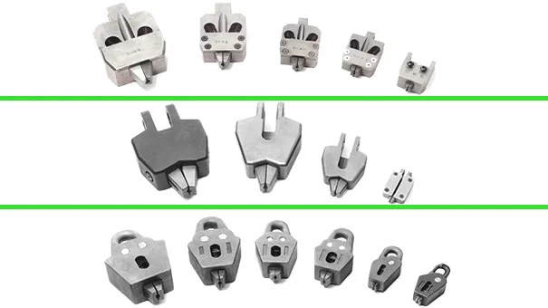
PULLER STYLE COMPARISON
Morgan-style
Robust, heavy-duty construction grip with capacities up to 1″ diameter and 40,000 lbs. of pull
- Simple spring loading to operate jaws simultaneously
- Elliptically designed spring seat to mount grip to standard lifting chain
- Heavy-duty construction to allow high die pull
- Optional clevis to enable tangent die pull
- Simple jaw design, easily replaced without tools
- Additional hook-up options are available
Typical Applications: Wire-drawing machines with a link chain and connected to the drawing block with an oblong link slipped over a post at the top of the block
Vaughn-style
Medium-duty construction grip with capacities up to 1.25″ diameter and 50,000 lbs. of pull
- One piece casting to make it lightweight
- Quick-release hook to release tension quickly from puller
- Simple jaw design, easily replaced without tools
- Additional hook-up options are available
Typical Applications: Wire-drawing machines with a leaf-style chain and a quick-release hook assembly for releasing tension after the pull. Larger sizes use link chain and oblong link hooks. NOTE: Vaughn style quick-release hooks must be used with Vaughn style blocks
Sleeper & Hartley-style
Light-duty construction grip with capacities up to .5″ diameter and 10,000 lbs. of pull
- Simple attachment to standard roller chain makes it economical
- Optional thumb release for single hand operation
- Simple jaw design, easily replaced without tools
- Additional hook-up options are available
Typical Applications: Uses a roller chain and a pin-type hook that fits into a radial hole in the drawing block. Thumb-release pullers are used to ease loading and unloading of the wire grip. Pulling the back latch retracts the jaws into the body and holds them open. Units are completely interchangeable with standard S&H grip heads
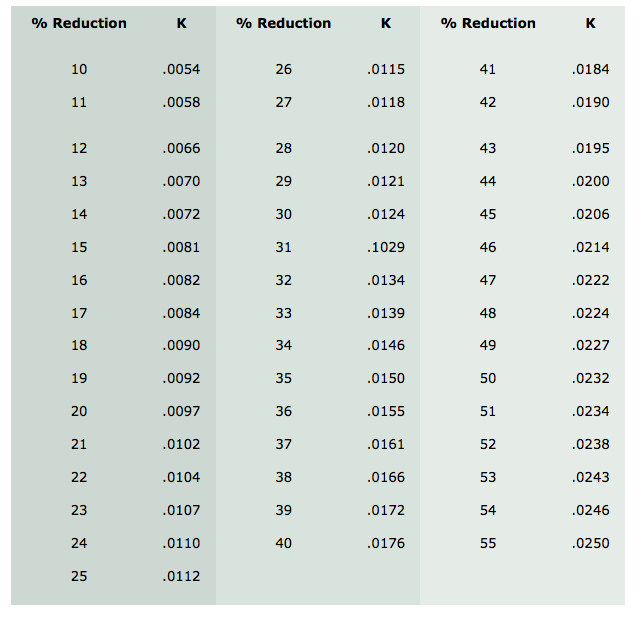
CALCULATING DIE PULL
Die-Pull Calculation:*
P=43.56d [2] x SK
P = die pull in pounds
d = diameter after drawing in inches (in)
S = tensile strength before draft, in pounds per square inch (PSI)
K = factor which varies with the percentage reduction as shown in K Factor—% Reduction Table below
K Factor—% Reduction Table**